3.User Interface
3.1.
Main Window Components

3.1.1 MainMenu
All NIS-Elements functions are accessible from the main menu at the top of the screen. Menu commands are grouped according to their purpose.
3.1.2 Toolbars
There is a default set of toolbars, each toolbar containing number of buttons. There is also one fully customizable toolbar - the main left toolbar - to which any button can be added. Every button or whole toolbar can be hidden by the user. Please see 3.3 Arranging User Interface for further details.
3.1.3 Status Bar
The status bar at the bottom of the screen displays the following information:
Figure 3.2. The application status bar
- This part of the status bar displays available layouts.
Note
The layout Tabs may be hidden when the Show Layout Tabs option in the 3.3 Arranging User Interface window is deselected.
- This status bar section displays the type of the currently selected camera.
- Here you can get information about the most recently performed command. The FPS / Exposure / Focus info is shown in case of live image. The black bar indicates the focus rate. Longer black bar represents more of the image in focus.
- This section show the name of the current objective.
- Current coordinates of XY (Z) stage are shown in this part of the status bar.
3.1.4 Docking Panes
Docking panes are square spaces inside the application window, where you can place (dock) any of the control panels. There is one docking pane available at the Right, Bottom, and Left side of the application screen.
To Display a Docking Pane
- Go to the View > Docking Panes sub-menu and select the pane you would like to display.
Note
The Docking Panes sub-menu can be also displayed by right-clicking into the empty application screen.
- The docking pane appears, either empty or with some window(s) docked inside.
- Repeat this procedure to display more docking panes.
Handling Control Panels
Various control panels can be displayed docked within the docking panes or they can be floating. See the following picture:
Figure 3.4. The Docked Control Panel Caption
To handle the control panels (CPs), you can:
Open recently closed CP Locate the button on the main left toolbar. When you click it, the list of recently closed CPs appears. Pick one to display it again.
Add CP to a docking pane Right click inside a docking pane (3) to display the context menu. Select the control panel to be displayed. If the window is already opened somewhere else (in another docking pane or floating), it closes and moves to the new destination.
Close CP Click the cross button (2) in the right top corner of the tab.
Drag CP Drag any CP by the tab and drop it somewhere. If you drop it by the edge of a docking pane, it will create another column of this pane. If you drop it over the caption of another CP, it will be docked in the same pane as a new tab. If dropped somewhere else, the CP will be floating.
A color frame appears when you place the mouse cursor dragging a CP over the edge of a docking pane or a caption of another CP. It indicates that if you drop it, its placement will be handled automatically.
Minimize the docking pane Click the arrows in the top left corner. The pane minimizes to a stripe by the edge of the screen. It can be restored to its original position by double clicking this stripe or by clicking the arrows again.
Close the docking pane Click the cross button (4) in the docking pane caption. Or you can right click the pane and unselect the Docking View option.
Dock/undock CP To dock (and undock) a CP, double click its tab.
Display CP Another way to display a CP is to go to the View menu and select the desired control panel. After that, the CP appears on the screen - floating or docked. Positions of the windows are being saved by the system so that each control panel appears in the same position as it was before it being hidden. The controls are sorted to several groups.
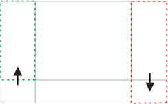
Shrink/Expand dockers Having more docking panes opened, a situation where there is not enough room for the control panels can occur. In such case, the Shrink and Expand commands shall be used.
- Right click the pane you would like to shrink/expand. A context menu appears.
- Select the Expand/Shrink command. When one of the panes shrinks, the neighbouring pane expands to the emptied corner and vice-versa.
-
- Image Window
Tools affecting the appearance of the current image are gathered within the image window toolbars (the top image toolbar and the right image toolbar). There are the following buttons by default:
Enable LUTs (L) Applies LUTs to the image. See 6.5 LUTs - Non-destructive Image Enhancement.
Keep Auto Scale LUTs Applies the AutoScale command to the image continuously.
Auto Scale Performs automatic setting of LUTs.
Reset LUTs Discards the LUTs settings.
Show LUTs window Opens the window with LUTs.
Pixel Saturation Indication Turns on/off pixel saturation indication without setting on/off LUTs. Select the highlighting color from the nearby pull-down menu for Oversaturated and/or Undersaturated pixels. See 6.2.3 Channel Coloring.
Open Attachment Opens a file previously attached and saved with the ND2 file. To attach any file to an image, right-click inside the image, select Add Attachment and choose a file to be attached.
Maximum size of the attached file is 64 MB. Context menu over the image also enables to Open Attach-
ment... (same functionality as the button), Save Attachment As... (saves the attached file separately) or Remove Attachment (attachment is removed from the ND2 file).
Mouse XY Requires a motorized stage. If turned on, the mouse cursor on a live image changes and you can control the XY stage by dragging the live image.
Fit to screen Adjusts zoom to view the whole image within the NIS-Elements D screen.
Best Fit Adjusts zoom to fit the image window in one direction and fill the available area with the image.
1:1 Zoom Adjust zoom so that one pixel of the image matches one pixel of monitor.
Zoom In Increases magnification of the image.
Zoom Out Decreases magnification of the image.
Show Probe This button activates the probe. The probe affects histograms, auto exposure and auto white balance functions.
Show Grid Displays the grid for rough measurements.
Show Scale Displays the image scale.
Show Frame Displays and applies the measurement frame. (requires: MEAS (Automatic Measure- ment))
Turn ROI On/Off Displays the Measurement Region Of Interest. (requires: MEAS (Automatic Meas- urement))
Show Profile Displays the Measure > Intensity Profile control panel. It allows you to specify a linear section in the image of which the pixel intensities graph will be created.
View LUT Intensity Displays the scale of intensities used inside the image. It works on monochro- matic images or a single image channel.
Show Annotations Displays the vector layer which typically consists of annotation objects (text labels, arrows) and measurement objects.
View Binary Displays the binary layer of the image. (requires: MEAS (Automatic Measurement))
View Color Displays the color layer of the image.
View Overlay Displays the color layer and the binary layer in overlay. (requires: MEAS (Automatic Measurement))
Tip
Right click the icons to invoke a context menu where properties of each tool can be modified.
Channel Tabs
Figure 3.7. Channel tabs of an RGB image
| |
| |
|
Status Bar
The status bar at the bottom of the image window displays the following information:
Figure 3.8. Status bar of the image window
- The first field of the image window status bar Image displays the calibration. See also 8.1.1 Calibration,
8.1.1.3 Units.
- Image bit depth (8bit, 12bit, 16bit, etc.) followed by Image size. You can change the displayed units from the context menu.
- Pixel coordinates of the mouse cursor along with channel intensities, Binary layer value (0 or 1) and the Color mode (RGB, Monochromatic, etc.).
-
- Arranging User Interface
Having a well organized application layout can help you make the work with NIS-Elements D very effective. There are the following options on customizing the appearance of NIS-Elements D:
Custom window placement All control panels (Camera Settings, Measurement, Histogram, LUTs, etc.) can be arranged inside or outside of the main application window.
Compact window or multiple windows The control panels as well as toolbars can be floating or docked on sides of the application screen.
Multiple monitor support The NIS-Elements D window can be stretched to occupy two monitors. When you switch from different application, NIS-Elements D will be activated on both monitors.
Customized toolbars Toolbar buttons may be added and removed from toolbars. See 3.6 Modifying Toolbars.
Maximizing the Image Area You can hide some of the GUI elements which are displayed by default:
- The channel tabs and the layout tabs may be hidden to save some screen-space. Display the 3.9 Appearance Options window and de-select the Show Channel Tabs and the Show Layout Tabs options.
- Image controls and the image status bar may be hidden. Use the Auto hide bottom toolbar option of the 3.9 Appearance Options window.
- When an image is displayed in great magnification, scroll bars automatically appear by the sides of the image window. You can hide them by de-selecting the Show Scrollbars context menu option.
-
- Layouts
A layout in the context of NIS-Elements D is a set of options describing the arrangement of control panels, toolbars, and menu items. Blue tabs representing active layouts appear in the application status bar. The following layouts are placed there by default:
- Full Screen
- Docked Controls
- Measurement
Other layouts can be added and managed via the Layout Manager. To hide/show the layout tabs within the status bar, go for View > Layout > Layout Manager and (de)select the Show Layout Tabs option.
To Create a New Layout
Figure 3.9. Layout tabs
- Modify the current layout so that it suits your concept of work.
- An asterisk * appears next to the layout name (to indicate it has been modified).
- Right click the layout tab and select the Save Current Layout As or Save As Default command. If you do not need to create a new layout but would like to save the changes made, just right click the current (asterisk-marked) tab and select the Save command from the menu.
- Write the new layout name and confirm it by OK .
- A new tab appears and the layout is saved to the list of layouts.
To Reload Previous Layout Settings
You may want to undo the changes made to the layout. Mostly, it can be done by the Reload command. Or by selecting the Load Default command.
- Right click the asterisk-marked (recently modified but not saved) tab and choose the Reload command. The application restores the last saved state of the layout.
- Right click the asterisk-marked tab and choose the Load Default command. The application loads the previously saved default layout.
-
- Layout Manager
Run View > Layout > Layout Manager to display the Layout Manager. The list of currently available layouts is placed on the left side of the layout manager. Each layout may contain information about controls, toolbars, menu, and commands to be performed when switching between layouts.
Figure 3.10. List of Layouts
Modifying the Layout Settings
- Select items within the Global Layout list which you want to be shared by all layouts.
- The check marks on the left of the layout names indicate the layout visibility. Select the ones you want to display in the application status bar.
- If an item within some particular layout is not selected, it means you do not want to customize it and the global settings - if selected within the Global Layout - will be used. If the item is not selected within the Global Layout either, the settings of the most recently active layout will be used.
- Set whether the layout is Private or Shared. If set Private, it will not be visible for other users. See
2.3 User Rights.
- Customize each item according to your needs (see below).
Layout Manager Tools
Create Layout Adds a new layout to the list of layouts.
Remove Layout Deletes the selected layout. The first two layouts cannot be deleted.
Set Layout as Active Makes the selected layout active.
Load Default Loads original settings of the selected pre-defined layout (Full Screen, Docked Controls, Measurement) so that it looks just like after the program installation.
Lock Layout Select a layout component and click this button to lock these elements so that they cannot be moved or closed. To unlock these components, click the button again or right-click the locked layout tab at the bottom and click Unlock Layout.
Apply to All Changes made on the currently edited layout are applied to all other layouts using this button. Global layout is not affected however changes made on the global layout are applied to other layouts.
Import Layouts Enables to load a previously saved set of layouts from an XML file. When you try to import a layout with already existing name, you will be prompted to choose whether: the imported layout replaces the existing colliding layout, or is not imported, or is imported and renamed.
Export Layouts The settings of layouts can be saved to an external XML file. Use this Export button. In the windows that appears, define the destination file name and check which layouts will be included in the exported xml file.
-
- Modifying Toolbars
Hiding Toolbar Buttons
- Display Layout Manager by the View > Layout > Layout Manager command.
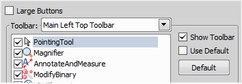
- Select the Toolbars item within the list of layouts. The right-side part of the window changes.
- Choose one of the toolbars which you would like to modify from the Toolbar pull-down menu.
- If selected, de-select the Use Default option on the right.
- Any button of the toolbar may be hidden by de-selecting it. No buttons can be added to any of the toolbars except the Main Left Toolbar.
- The whole toolbar can be hidden by de-selecting the Show Toolbar check box.
- There are two sizes of buttons available. Select the Large Buttons option to use the larger one. This setting is shared by all toolbars.
Adding Buttons to the Left Toolbar
Custom user buttons can be added to the main left toolbar. You can define your own buttons which run single macro functions or execute macros. Select the Main Left Toolbar from the pull-down menu.
Let's say that we very often use the Image > Contrast command. It is useful to add a shortcut button to the toolbar.
- Press the Add button, and choose Command from the pull-down menu:
- A new command - Command 0 - is added to the list.
- Now, assign a macro command: Open the pull-down menu on the right side of the Command edit box and click Command List.
- A list of commands appears. Choose _Contrast().
- Confirm the selection by OK .
-
- Modifying Menus
The Main Menu and some of the Context Menus within the application window may be modified. Items of the context menus can be hidden by de-selecting them similarly to the toolbars. The main menu can be modified as follows:
Modifying the Main Menu
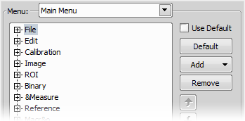
- Display Layout Manager by the View > Layout > Layout Manager command.
- Select the Main Menu in the topmost pull-down menu.
- Any item may be added to the main menu - a Separator, a Menu Command, a sub-menu (Menu Popup), and even a new menu (Main Menu Popup) - by the Add button.
- Select the existing menu item under which you would like to place the new item.
- Click the Add button and select the item to be added from the pull-down menu.
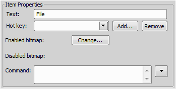
- Edit the Item Properties.
| |
| |
|
Text This is the text which appears in the pull-down menu. You may add “&” before any letter - such letter will be considered a keyboard shortcut when browsing the menu.
Hot key One or more hot key shortcuts may be assigned to the command. Just press the Add
button and press the key combination. Press Remove to remove the selected hot key.
Enabled/Disabled bitmap, Command These fields serve for assigning a bitmap image and a macro function to the menu command. It works the same way as when modifying the Main Left Toolbar (described above).
Note
The Default button discards all changes and loads the main menu original configuration. The Remove button deletes the selected item. The arrow buttons move the selected item up/down. The Use Default check box, when selected, applies the default settings to the menu.
-
- Running a Macro Upon Layout Change
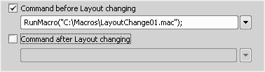
A macro command or a macro can be run upon layout change.
- Display the layout manager by the View > Layout > Layout Manager command.
- Select the layout by displaying of which the macro function will run and select the Commands check box.
- The following box appears on the right side:
- Select the timing. The “before” option will run the command when you click on the layout tab, but before actually changing the layout. The “after” option runs the command right after the layout is changed.
- When the field is enabled, type the command or insert it via the pull-down menu.
-
- Appearance Options
General appearance adjustments can be made in the Options window. Run the Edit > Options
command and switch to the Appearance tab.
Background Background of the main screen may use default tiles or custom color.
Color scheme There are the following color schemes predefined within the application: Light scheme, Dark scheme, Black scheme.
Language Select the language to be used in GUI. The language pack is a part of the Local Option feature set.
Prompts on Image Save dialog Actual words used on buttons of the window which appears if an image has been modified and is about to be closed.
The Z value displayed in status bar Having two Z devices, select whether to display Z1, Z2 or both on the main status bar.
Close ND Acquisition window after Run The View > Acquisition Controls > Capture Timelapse window will be closed automatically upon acquisition start.
Image window toolbars You can decide whether the top and side image toolbar is integrated into the main toolbar (Common for all Images) or whether each image has its own set of toolbars (Visible for each image). The most space-saving option is to use shared toolbars and hide the image status bar and the ND2 control bar (6.3.1.1 Control Bar) automatically (Common for all images, auto hide bottom toolbar). It will show up only when the mouse cursor rolls over the bottom part of the image.
In the Right Toolbar section you can select the appearance of buttons having more sub-options. See
3.2 Image Window.
Auto hide bottom toolbar This option hides the image status bar and the ND2 control bar (6.3.1.1 Control Bar) automatically. It is displayed only when the mouse cursor rolls over the bottom part of the image picture.
Show channel tabs Show channel names and colors in the image window status bar.
Show Layout tabs Show layout tabs in the main status bar.
Show Task Bar If unselected, the Windows taskbar will be hidden.
Default vertical docker on the right/left side Select the preferred side for the default vertical docking pane.
Keep text size while zooming When selected, text annotations will not be zoomed with the image. See
View > Analysis Controls > Annotations and Measurements .
Allow zoom factors lower than best fit When selected, the image can be resized to be smaller than displayed using the View > Zoom > Fit to Screen command.
Lock camera magnification If you are used to switch between two camera modes (resolutions), this option ensures that the scene observed does not change its size or position.
Keep picture window aspect If checked, the image window respects the image size while zooming.
Initial Zoom You can select the zoom factor of the newly opened images. The options are Best Fit, 200, 100, 50, 25%.
Initial zoom 100% for Live and Capture Whenever a new Live or Captured window is opened, the zoom will be automatically set to 100%.
Default Volume View Rendering Engine Switch between the Old/New engine used in the Volume Viewer.
3.10 Simplified User Interface
After the Industrial GUI module is installed, a simple layout intended to be used in industry imaging applications is added to the application. Switch to the layout by the Simple button in the top right corner. Return to the main layout by the same button (which is changed to NIS-D ).
Note
This button corresponds to the View > Simple Control menu choice.
A Nikon-manufactured digital camera (DS-U1/U2/U3, DXM1200C, 1QM) must be connected to NIS-Elements D in order to display the View > Simple Control command.
3.10.1 Behavior
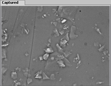
- The “Live” and “Captured” images can be switched between the main image area and the preview window on the right.
- The number of control panels available within the docking panes is reduced.
- The main toolbar is reduced, some buttons are added. See 3.10.2 Toolbar Buttons.
3.10.2 Toolbar Buttons
The following toolbar buttons are added to the layout:
Print This button sends the current image (the large one) to the default printer. Invoke the nearby pull-down menu to set printing properties. See File > Print .
Change View This button swaps the Live and the Captured images between the main image window and the preview window in the right-side docking pane.
Show Graticule This button has been moved here from the right image toolbar of the main view and provides the same functionality. See 3.1 Main Window Components.
Show Scale This button has been moved here from the right image toolbar of the main view and provides the same functionality. See 3.1 Main Window Components.
3.10.3 Camera Control Panel
The Live button displays live image in the picture window. The second button either captures a single image after clicking the Capture or captures a single image and saves it to the Auto Capture
Folder automatically after clicking Auto Capture (check the Auto Capture (Auto Save) option in the
Save control panel).
3.10.4 Save Control Panel
This control panel enables the user to specify image saving options. Most of the settings only applies when the Auto Capture (Auto Save) option is checked.
| |
| |
|
Directory Press the ... button and select the Auto Capture Folder where images captured by the button will be saved.
Make Subdirectories Automatically The images can be sorted to subdirectories automatically based on the time of acquisition. Select this option and use place-holders from the drop-down menu to specify
the right format (click to display the place-holder legend). E.g.: “$YYYY$MM$DD” would create a new subdirectory for each day named like this: “20150103”.
Prefix, Next File, Digits Type the prefix and numbering style intended for the files being saved automat- ically. The Next File field 1/ informs you and enables you to change the number which will be used for the next automatically saved image.
File Format, Compression Select the file format to save the images in. Some formats enable you to set the Compression parameter. It is recommended to use either “none” or “lossless” in order to preserve good image quality.
Ex. The path and file name of the next image to be saved is displayed here.
Auto Capture (Auto Save) Check this option and a new image will be created and saved to the Auto Capture Folder each time you press the Auto Capture button.
Burn Annotations This option determines whether the annotations created by the tools of the Annotations and Measurements window will be included in the saved file.
Warning
The separate annotation layer will be merged with the image data.
3.10.5 Preview Control Panel
The Live or Captured image is displayed within this window. Use the Change View button of the main toolbar to select which one.
4. Cameras & Devices
Cameras & Devices
-
- Basic Workflows
4.1.1 Camera Selection on Startup
Let's assume the camera works properly, is connected to the PC with proper system drivers installed and running (if required by the camera).
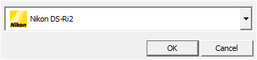
- Select Camera Driver
You will be asked to select the camera driver every time you launch NIS-Elements D. You can change the driver later using the Acquire > Select Driver command. Choose the driver that matches your camera:
- Select Camera Type
Color cameras can be used in a monochromatic mode. The actual camera type (color/mono) can be selected by the Acquire > Select [Camera Name] command.
Note
The emulated monochromatic mode is optimized for use with fluorescence specimen where often only a single-color signal is being captured. The following formula is used to compute intensity of the emulated mono image:
I = (Ir * Wr) + (Ig * Wg) + (Ib *Wb)
Where: W is channel weight calculated from the channel histogram and I is channel intensity. W ensures, that channels containing some signal are accentuated while channels without signal are suppressed. As a result, depending on conditions, the brightness of a monochrome image might not change even if the lamp light intensity is changed.
- Adjust Camera Settings
Exposure time, camera resolution, and other camera-specific features are adjustable from the
Camera Settings window. To invoke it, use the Acquire > Camera Settings command.
4.1.2 Optical Configurations
4.1.2.1 Introduction to Optical Configurations
Typically, a laboratory computer image analysis system consists of a computer, a camera, and a micro- scope equipped with certain accessories (objectives, filters, shutters, illumination, rotary changers, etc). Most of the mentioned microscopic hardware can be motorized and therefore can be controlled via NIS- Elements D. In addition, it is possible to integrate single settings of all these devices into one compact set called Optical Configuration. It is recommended to create several optical configurations containing particular devices settings. Then a single click can completely change the current hardware configuration.
4.1.2.2 Creating New Optical Configuration
- Please check that all the devices (microscopes, cameras, etc.) which you want to associate with the new optical configuration are properly attached to the system and working.
- Choose the Calibration > New Optical Configuration command. In the window which appears, adjust the settings of the devices to match the intended state which will be saved to the optical configuration.
- Type the name of the new optical configuration to the Name field. Use a short descriptive name, the name is used on the button in the main toolbar when you select the Show on toolbar option.
- In the left column, select which device settings to associate with the Optical configuration.
Camera setting A list of the current camera properties appears on the right. It is being updated dynamically.
Use Stored ROI If you want to include the camera ROI settings, select this option. Status of the camera ROI (ON/OFF) and its size will be set when switching to this configuration.
Channel setup These settings determine how channels of newly captured images will be named and what color will be assigned to them. The available properties depends on the current camera setup (color/mono). In the mono camera mode, you can either assign the name, the emission length and color to the channel Manually, or leave this task to NIS-Elements D (the Automatically option). In such case, information of the light path (emission wavelength) will be used to determine the channel name and color.
Microscope setting If there is more than one shutter available and you would like to associate a shutter with the optical configuration, select which one is the Active Shutter from the pull-down menu. Select which parts of the microscope shall be included in the configuration by checking them in the Used devices dialog box.
| |
| |
|
Note
Active shutters remember their aperture setting and display it in the Microscope setting section
Objective An objective mounted to a motorized nosepiece can be included in the configuration. Select the objective from the pull-down menu. Objectives which are currently assigned to any pos- ition of the nosepiece are listed. See 4.1.3 Objectives.
Note
The objective must be assigned to a nosepiece position via the microscope control pad or the nosepiece control panel beforehand.
-
|
Camera & Devices Controls
|
|
If some of the device settings still need to be adjusted, click the buttonand select the appropriate control panel from the pull-down menu. Adjust the settings within the control panel, the optical configuration will be updated automatically.
- Click Finish to save the new optical configuration and to close the window.
- You can create more optical configurations by repeating the procedure. The optical configurations are saved to registry immediately. A backup of optical configurations can be made by running the
Calibration > Optical Configurations command and clicking the Export button.
4.1.2.3 Managing Optical Configurations
To display the optical configurations manager window, run the Calibration > Optical Configurations
command. You can make the following actions from the window:
- Create, duplicate, rename, delete, copy settings and switch between optical configurations.
- Modify optical configuration properties.
- Import and export optical configurations to/from an XML file.
4.1.2.4 Operations with Optical Configurations
Once created, the configuration appears in the list and can be shared with other users by changing the Private option to Shared (see 2.3 User Rights). The following operations can be performed on the selected configuration:
- It can be deleted by pressing the Remove button. A confirmation dialog box appears.
- Its name can be changed by the Rename button. A button with the configuration name appears in the toolbar (if the Show on toolbar option is selected).
The configuration settings may be transferred to another optical configuration by thePress the button and select the optical configuration to be overwritten with the current one.
- A copy of the configuration can be made via the Duplicate button.
button.
- The configuration can be applied to by the Set As Active button.
- The settings of all optical configurations can be exported to an external XML file using the Export
button.
- The previously exported optical configurations settings can be loaded from the XML file via the Import
button.
- The list of optical configurations can be ordered manually using the arrow-up and arrow-down buttons.
- Each configuration can be arbitrarily modified within the right-side portion of the window.
The optical configuration buttons are available in the main toolbar when Show on toolbar option was selected during the setting process.
4.1.2.5 Using Auto Exposure while Switching between Optical Configurations
You can use one optical configuration when working with live image and switch to another optical con- figuration just for the image acquisition, very often, this is performed automatically i.e. by a macro command. If the “on-acquisition” optical configuration has the Auto Exposure camera mode turned ON, it may produce over- or under-saturated images.
Since the Auto Exposure algorithm estimates the optimal exposure time by analyzing several last frames, it is not able to make the estimation correctly if the change of optical configurations would cause signi- ficant change in image brightness. To prevent this, we recommend to use Manual Exposure mode in the optical configuration used for capturing.
4.1.3 Objectives
If you want to perform measurements on captured images it is wise to calibrate all objectives used to capture images. Whenever an image is captured through a calibrated objective, the image inherits its calibration.
4.1.3.1 Managing Objectives
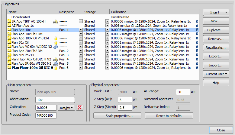
Run the Calibration > Objectives command. The Objectives window appears:
| |
| |
|
A list of used objectives can be created within the Objectives window. For each objective, the objective
name, position in the changer, storage status and the calibration are displayed. A Calculator icon next to the calibration value indicates that the calibration has been calculated from objective properties. If the calculator icon is missing, the calibration has been performed manually. Use the buttons on the right side to manage the objectives:
Insert Click the button and select one of the objectives from the database (ordered by magnification). Custom objectives can be added to the database via an INI file.
New Press this button to create a custom objective. The new objective will be added to the list. Then, define the Main properties and the Physical properties of the objective.
Duplicate If zoom is used, the objective calibration must be re-calculated accordingly. Use this button to make a copy of the objective and define the zoom factor in the window which opens.
Remove This button deletes the selected objective.
Recalibrate Starts the calibration of the selected objective. See 4.1.3.3 Objective Calibration.
Export Enables you to export the complete list of objectives to an XML file. The standard Save As window appears.
Import This button enables you to import a complete list of objectives from an external XML file previously created by the Export button.
Current Unit This button invokes a pull-down menu where units for the whole application can be selected.
Help Displays a help page to the Calibration > Objectives command.
Edit the properties of the selected objective in the bottom part of the window. Press the Close button to finish this window.
4.1.3.2 Assigning Objective to a Nosepiece Position
- To assign an objective to a position or to change an attached objective assignment, click the setup button in the nosepiece section of the microscope control pad.
- A window appears which enables you to select one of the available objectives to the corresponding position.
- Each objective has its specifications displayed in the table. These specifications are not editable.
4.1.3.3 Objective Calibration
After you press the Recalibrate button in the Objectives window or when creating a new custom objective, the following window appears:
Select one of the calibration methods:
- The Manual calibration lets you draw a distance into a picture and assign real length to it. The live image starts automatically and a window appears. Proceed to: 4.1.3.4 Manual Calibration
- If a motorized XY stage is available, the Auto and 4 points automatic buttons appear. Proceed to
4.1.3.5 Objective Calibration Using XY stage.
Press to continue...
Superresolution Calibration
This type of calibration is available after successful manual or automatic calibration. It triples the camera's resolution and uses fine stage movements to improve the resulting objective calibration. Click the
button and wait till the objective calibrates.
4.1.3.4 Manual Calibration
Manual calibration requires the user to specify a distance in the image. It can be either a measurable distance or the size of one pixel. The following procedure can be used for different purposes:
(Re)calibrating an objective (see 4.1.3.3 Objective Calibration)
- (Re)calibrating of a microscope zoom
- When performing a manual calibration, the following window appears:
2)
-
- If you know the size of one pixel, click the
button.
Enter the value and finish the calibration by the button.
-
- If you do not know the pixel size, you will need to specify distance in the image. For this purpose, use an image of a calibration slide or a ruler captured with your current system configuration.
- The distance is defined by placing lines to the image. If you are sure the calibration pattern is per- pendicular to image edges, it is recommended to select either vertical or horizontal lines. Otherwise, select the parallel lines .
- Click into the image to place the first line and then the second line to specify the distance:
, You can modify the line position while holding the primary mouse button. After you release the button no further changes can be made. Place the second line in the intended position by an- other click.
Draw the first line by clicking twice inside the image. The line can be moved and adjusted arbitrary by mouse. When satisfied, finish the first line by right-click. The second line can be placed by an- other click to the image, this time only to adjust the distance from the first line. The process is completed by right-click.
- The following dialog box appears
- Enter the distance between the two lines and select correct units.
-
Click to finish the calibration.
4.1.3.5 Objective Calibration Using XY stage
This procedure requires a motorized stage. Select one of the following methods:
Auto The Auto method is fully automatic. Calibration is performed on a part of the live image marked by red square that is shown before the calibration is launched. You can also choose the channel to be used by auto-calibration.
Figure 4.7. Auto-calibration window
NIS-Elements D moves the motorized stage, acquires two images, and calculates the calibration from the shift of the images. The auto-calibration performs an estimation of the real relay lens zoom factor. If the estimation does not match the value specified within the Acquire > Camera Light Path window, a warning appears.
Figure 4.8. Example of the warning message
It is recommended to cancel the auto calibration (click No ), check the real zoom factor of your relay lens and check and correct the relay lens settings within the Acquire > Camera Light Path command window.
Note
The success of this method depends on the texture of the specimen, its contrast, illumination, etc. If the combination of these factors is unsuitable, the auto calibration may fail. If it fails, try the fol- lowing:
-
- Move the stage to another area of the specimen to get a better texture.
- Improve contrast by setting LUTs.
- Check focus, re-focus if needed.
- Turn on the Acquire > Shading Correction > Shading Correction command ON.
4 points If you select the 4 points method, the system draws four points on the screen (subsequently) and asks user to move one significant part of the specimen to each position. After all four steps are completed, the calibration is calculated from the moves of the stage.
4.1.3.6 Monitor Calibration
NIS-Elements can compute the real zoom factor of a properly calibrated image. The monitor calibration must be correct:
- Display a context menu over a calibrated image and select the Show Physical Zoom command. The “real zoom” value appears in a box in the top left corner of the image.
Note
If the current image is not calibrated, the box will contain N/A.
- Right-click the box with the zoom value and select the Monitor Calibration command, the following window appears.
Figure 4.9. Monitor Calibration Dialog
Caution
The dialog displays calibration of the monitor on which it is displayed. If you have multiple monitors, move the dialog between them.
- Check Width and Height values and whether they match the real size of your monitor.
Tip
The detected monitor type is displayed in the window. If the information about the model is precise, it is likely that the automatic calibration is correct, otherwise, we recommend to switch to User monitor calibration.
- If you are not sure whether the detected calibration is correct, select User monitor calibration. Take a ruler or a measuring tape and measure width and height of your monitor. Enter these values and
confirm the calibration by the button.
4.1.4 Connecting a Device to NIS-Elements
Before you get to work with NIS-Elements D, all hardware accessories should be connected properly to the system. In most cases, the following basic procedure is sufficient to connect a device successfully:
- Install NIS-Elements D, and select the appropriate device(s) during the installation.
- Connect the device to the PC and switch the device ON.
- Run NIS-Elements D, and run the Devices > Devices Manager command to open the Device Manager.
- Use the Add button to add the device to NIS-Elements D.
- Select the device from the list of installed devices and press the Connect button.
- Select logical devices to be activated.
- Configure device-specific settings using the Configure (physical) Device and the (logical) Device Parameters buttons.
- Close the Device Manager
-
- If a peripheral device is connected to NIS-Elements, some extra commands and features become available. This concerns typically motorized XY stages and Z drives, but also other devices.
Note
MULTIZOOM AZ100M, ECLIPSE LV series, ECLIPSE MA200, or ECLIPSE L200N/300N microscopes
can not be connected from NIS-Elements while the setup tool of each microscope is active. To connect any of these microscopes to NIS-Elements, exit the setup tool and then run the NIS-Ele- ments.
Renaming of devices
Either logical or physical device can be renamed by user. Just right-click the device name and select the Rename Device command from the context menu. The user-defined names can be handy in two cases:
-
- You are using two logical devices having matching names, but you need to uniquely identify them (e.g. from macro).
- You are used to call a device with another name and would like to rename it in order not to be confused by the predefined name any more.
4.1.5 What are “Logical Devices”?
NIS-Elements D handles hardware accessories using the concept of logical devices. There are features of different hardware devices which equal and therefore can be controlled equally. Such features are called “logical devices”. A typical logical device is Stage XY. Different microscopes can be equipped with different XY motorized stages, although - regarding the user interface - they behave equally. One phys- ical device (a piece of hardware) can contain one or more logical devices the list of which appear in the Device Manager after the connection is established.
Available Logical Devices
Analyzer The analyzer is a polarizing filter placed in the optical path between the specimen and the lamp. The logical device offers two states: ON (inserted) and OFF (extracted).
Aperture This logical device is used for controlling apertures in the light path. It is used in complex mi- croscopes rather than as a standalone device. Two parameters can be typically set for aperture devices, the state (on/off) and aperture size.
Condenser A condenser is a two-lens combination located next to the illumination source in the optical path. Its purpose is to collect light and direct it to the specimen being examined. The corresponding lo- gical device relates to a changer of different condensers.
Filter This logical device controls filter changer movements. There can be several filter changers con- nected to NIS-Elements D at a time. Each filter changer needs to be set up - filter types shall be assigned to positions of the changer- Display the filter changer control panel (Devices > Filters and Shutters or Devices > Microscope Control Pad )
- Click the settings button , a window appears.
- Select one of the available positions which the filter will be assigned to.
-
Click the button, a list of available filters appears.
- Select the filter name from the list and confirm it by OK .
- The filters can be moved within the already defined positions using the Up/Down arrow buttons.
Note
When browsing the list of filters, details about the currently selected filter are displayed on the right side of the window.
Illuminator This logical device is used for controlling the specimen illumination remotely. There is no standard dialog box for the illuminator control. Each device handles this logical device via a user interface specially designed for it - typically containing one button for switching it on/off and a slider for regulating intensity.
Light Path Some microscopes have more than one port where it is possible to attach a light source or a camera. This logical device can switch the illumination between these ports.
Microscope This logical device is used to group standalone logical devices used in certain microscopes. To control the logical devices of a microscope from one control panel, select the Devices > Microscope
Control Pad command.
Nosepiece This logical device serves for controlling microscope objective changers. There can be three nosepiece types attached to a microscope:- Manual - it can not be controlled via the software.
- Intelligent - the current nosepiece position is read by the application, but can not be controlled.
- Motorized - such nosepieces can be fully controlled via the Microscope Control Pad or the Nosepiece
- control panel.
See 4.1.3.2 Assigning Objective to a Nosepiece Position.
ND Filter A neutral-density filter is a light absorbing filter whose absorption spectrum is moderately flat. It is used to reduce the illumination intensity within the optical path. The logical device offers two states: ON (inserted) and OFF (extracted).
PFS Perfect Focus System - this logical device corresponds to the PFS physical device available with Nikon TE2000/TI microscopes.
Shutter This logical device can control shutters installed in your system. This device is handled via the Devices > Filters and Shutters control panel or straight from the microscope control pad. You can select the type and rename the shutter by running a contextual menu command either within the Filters & Shutters control panel, Device Manager window, or in the main toolbar.
Note
There was a restricted number of shutters which could be connected to the system in previous releases of NIS-Elements D and they were identified by Type (DIA, EPI, Aux1, etc...). The current
version supports identification of shutters by custom Names, but the Type attribute can be still found in some windows (or used in some macro functions). This is to ensure backward compatib- ility.
Zoom This logical device is used for controlling the zoom factor. Run the Devices > Zoom Configuration
command to adjust the zoom settings.
Stage XY Stage XY enables the movement of specimen within X and Y axes. The system offers user to control stage movements.
Stage Z The Z Drive device enables movement throughout the Z axis direction.
4.1.6 XY Stages and Z Drives Tips
Please read the following tips for using motorized XY Stages and Z Drives.
Motorized Stage Initialization
A motorized stage being initialized could strike the objective. Before initializing the stage, make sure that the objective is away from the stage. If a motorized Z drive is available, use the Devices > Objective Clearance command to prevent this.
Setting Software Limits to Stage Movement
Some microscopes enable you to reduce the range of movement of the motorized stage by setting limits within the configuration window.
- Display the configuration dialog window (within the Devices > Devices Manager window).
- Move the stage to the position where the limit shall be set.
- Click the appropriate button.
- Set all the limits by repeating this procedure.
Caution
This procedure can not be used if you already set some limits and would like to broaden them at the same time. NIS-Elements D will not allow you to move the stage to any out-of-limits position. What you need to do is to reset the limits within the configuration window beforehand.
Using two independent Z Drive devices
Workstations can be equipped with two independent Z drive systems, one coarse (slow) and the other fine (fast). Typically, the first one is used for specimen manipulation in Z axis, when changing objectives, etc., the second one is used for auto-focusing. The following text explains how NIS-Elements handle the two Z drives.
Absolute Z The current positions of both Z drives (Z1, Z2) and the absolute Z position (sum of Z1 and Z2) are displayed in the main status bar. If there is not enough space to display all these values, only the absolute Z value is displayed (Z1 and Z2 still appear in a tool-tip). The absolute Z value appears in the Z Series Setup.
Active Z
The concept of Active Z enables user to select the preferred Z drive:
- The active Z drive is used when performing auto-focus.
- The Devices > Enable Mouse Joystick Z in Live command applies to the active Z.
You can select the Active Z device in the Devices > Mouse Joystick and Auto Focus Z menu.
Regular Z drive + Piezo Z drive
If you have a regular Z drive and a Piezo Z drive installed, some functionality is added:
- The Move Piezo Z to button is added to the Z Series Setup window when Piezo Z is selected.
- The Devices > Keeps Z position and centers Piezo Z and the Devices > Move Piezo Z to Home Position
commands appear in the Devices menu
The button and the Devices > Keeps Z position and centers Piezo Z command provide corresponding functionality. They move the Piezo Z device to its home position, and compensate this shift by moving the second Z drive in order to maintain the absolute Z position.
4.1.7 Camera Settings
A digital camera mounted to a microscope port records images of the observed scene on a light-sensitive sensor, and transfers them to a computer. NIS-Elements D supports various cameras differing from each other in resolution, frame-rate, sensor type, etc. Despite these differences, controlling different cameras is similar. The following features are included in the View > Acquisition Controls > [Camera
name] Settings window depending on a particular camera type.
Note
The complete list of cameras and devices supported by NIS-Elements is available in a separate document.
Reference of Common Camera Settings
1 frame for Fast Timelapse The camera head is equipped with 4 GB of memory available for fast cap- turing. Use this button to run acquisition with maximum available frame rate. However, the size of image sequence is limited to 4 GB.
Note
The actual frame rate depends on other settings (readout mode, sensor mode) and is limited by the read-out speed of the camera sCMOS chip. Maximum frame rate can be achieved with the combination of Rolling shutter and Overlap sensor mode.
AE Compensation In automatic exposure modes, the compensation affects how optimum exposure settings (Exposure time and Gain) are calculated. The Compensation value is expressed in Exposure Values (EV). Setting the compensation to + 1.0 EV makes the image twice brighter (e.g. doubles the Exposure time or Gain).
AE Lock This option makes the automatic exposure mode to lock the current exposure settings (Exposure time and Gain).
Analog Gain Controls the Gain (Sensitivity) of the camera and strength of the camera analog signal before it is digitized. This setting affects image brightness.
Auto White Balance (AWB) This button performs an automatic white balancing. It calculates the right values and then adjusts the red, green, and blue image components in order to get a neutral white color. The Auto White gives the best results on color neutral (gray) scenes.
Averaging Averaging is a commonly used technique of decreasing noise in the image. In this method 2, 4, 8 or 16 consecutive frames are averaged together.
Binning The binning mode provides considerably enhanced camera chip sensitivity by integrating more elements (pixels) together. E.g.: binning 4x4 integrates the signal from the area of 4x4 chip elements to one pixel of the resulting image. Smaller resolutions and faster frame rates are achieved using the binning modes.
Capture Bit Depth Channel Select per-channel bit depth used for capturing.
Clear Cycles This option enables you to decide, how many times the CCD chip should be cleared (reset). The set Clear Mode determines how often it is performed.
Clear Mode Sets how often the CCD chip will be reset. Please, see the camera user manual for further details. These options are available:
- Automatic
- Never
- Pre-exposure
- Pre-sequence
- Post-sequence
- Pre and Post-sequence
- Pre-Exposure and Post-Sequence
Commands > ROI > Use Current ROI Turns the camera ROI on/off. See 5.3 Camera ROI.
Contrast Affects dynamics of how the luminosity is rendered. There are several modes for different illu- mination (contrast) scene situation.
Conversion Gain This is a hardware pre-amplifier gain.
Cooling The Qi1/Ri1 camera heads are equipped with a cooling system that enables to cool down the CCD chip by -5° or -10° of the current room temperature.
| |
| |
|
Warning
When cooling by -10°, there might be a risk of water condensing inside the camera head (depending on humidity inside the room).
Desired Temperature Sets the target temperature of the CCD chip.
Detector Mode
Only in 12bit mode
Timed A common mode for capturing images.
Strobe If the camera controller is equipped with DS-RC switch, this mode needs to be selected to use the switch for capturing images.
Dynamic Range Dynamic range of a camera sensor is defined by the largest possible signal that it can generate divided by the smallest possible signal. Higher bit dynamic ranges bring wider ranges of grayscale levels from each camera pixel.
EM Gain Multiplier EM gain allows weak signals to be multiplied before any readout noise is added by the output amplifier, hence rendering the read noise negligible. There is a complex relationship (approx- imated to an exponential) between the value set and the actual level of multiplication. Typically, optimal signal-to-noise ratio and dynamic range is achieved between x1 to x300 EM Gain. When the setting ex- ceeds the value of 300, the field gets highlighted red in order to notify you.
Exposure, Exposure Mode Exposure mode determines how the Exposure time is calculated. Usually, the user can select between the automatic and the manual mode:
Auto Exposure Automatically calculates the exposure time in order to achieve optimal brightness of the scene. Image quality is the priority, therefore longer exposure times are preferred.
| |
| |
|
Note
Depending on particular light conditions, the result of auto exposure may not be optimal for image acquisition.
Warning
Under- over-saturation may occur when switching between optical configurations. Please see
4.1.2.5 Using Auto Exposure while Switching between Optical Configurations.
Note
Available exposure time range depends on the selected Format and Readout Speed.
Manual Exposure User selects both Exposure time and Gain manually.
Continuous AE When selected, the automatic exposure time is calculated continuously. If brightness of the scene changes, the exposure time is adjusted so that the live image is not over- or under- saturated.
Exposure Time Exposure time is the time of charge accumulation in a camera chip between two adjacent frames. Prolonging the exposure time increases brightness of the image as well as its quality (there will be less noise).
Fast (Focus), Quality (Capture) The software enables to create two resolution presets - Fast used for live image and Quality used for capturing. The formats then differ in image size, and consequently in frame rate (number of frames per second - fps). The higher the resolution is, the lower frame rate can be achieved. Available resolutions depend on the camera type.
| |
| |
|
Note
When switching between the formats while observing the live image, the size of the image on the screen is maintained - the zoom setting is changed instead. Only in some special cases, the beha- vior changes and the image size is changed instead of the zoom setting which is maintained.
FOV Size FOV of a camera which has the sensor larger than the image from the microscope port (imaging circle) needs to be reduced. Otherwise, images captured with a too-large FOV Size would contain visible vignetting (will be darker at the periphery).
Figure 4.10. Correct setting of FOV Size
| |
| |
|
16 mm Suits most conventional microscopes
22 mm Suits the Nikon Ti2-E microscope equipped with two filter-turrets.
25 mm Suits the Nikon Ti2-E microscope equipped with a single filter-turret.
Gain Controls the camera sensitivity. Increasing the gain increases brightness of the image, but decreases quality (the more random noise, the more streaky noise and color unevenness), and increases the frame rate indirectly by enabling shorter exposure times.
Gamma The gamma correction maps the intensity of live signal exponentially to the gamma parameter. For gamma < 1, dark portions of the image are enhanced whereas for gamma > 1, image parts of higher intensities are enhanced.
High Quality Capture When this option is checked, images are not processed by the camera control unit, but are sent to the computer in a RAW format. The computer then processes the images into the RGB format. This mode produces images with less noise and better color fidelity. Of course, transfer of the RAW data is slower than the normal mode which causes a lower maximal frame-rate.
Hue Hue shifts image colors across the rainbow.
Internal Shutter This option sets behavior of the camera internal shutter.
Opened Internal shutter is opened upon NIS-Elements and stays opened through the whole session. Only with one exception: if the Readout Mode is set to Normal 80kHz at 16bit, the shutter stays closed and opens only for exposures.
Closed Internal shutter is closed upon NIS-Elements startup and gets opened only for exposures.
Automatic Shutter is closed when the NIS-Elements is running. It opens only for acquisition.
Isolated Crop Mode This option turns on the Isolated Crop Mode described within the Andor document- ation. In this special mode, the size of chip is reduced and very high frame-rates can be achieved.
Keep Overlapped If checked. The Clear Mode and Sensor Mode boxes are set to Automatic and become disabled. This mode produces maximal frame rate and decreases the list of exposure times (in the camera settings window). Only the times of 1 frame and longer become available.
Limit Max. FPS to Insert maximum frame rate (frames per second) you would like to use, this will prolong the total duration of the time-sequence in exchange for the reduced frame rate. This option may be useful especially when using the 1 frame for Fast Timelapse button with a small region of interest. Then the frame rate could get unreasonably high.
| |
| |
|
Note
The Limit MAX FPS is possible only when camera is in Normal mode (not overlapped), the maximum fps in normal mode is shown next to the edit box.
Live Acceleration If the exposure time is too long, Live Acceleration helps you to make it shorter. The system automatically shortens the exposure time (so the frame rate rises), and the loss of intensity is compensated by increasing the gain (software multiplication). This procedure is not used upon Capture.
Maintain Temperature on Camera Shutdown If this option is checked, the camera maintains its tem- perature until the computer workstation shut down. The temperature will be maintained for example during NIS-Elements restart or when another camera is selected.
Max gain Maximal camera gain.
Maximum Exposure This is a safeguard of the time of the Auto Exposure. For quick exposure, it is con- venient not to set this value too high.
Metering Mode If this option is available, auto exposure can be calculated with an emphasis on over- exposed peaks (Peak) or average pixel intensity (Average).
Mode Defines how the Auto Exposure is performed. Average is suitable for bright field and Peak is better used for dark field.
Multiplier Controls on-chip multiplication gain. There is complex relationship (approximated to an expo- nential) between the multiplier value and the level of multiplication - in other words, the value 2 does not mean the signal is multiplied two times.
Noise Reduction If activated, it reduces noise generated by higher gain. NR works on interframe basis so you may notice some shadows on moving objects.
Offset Sets the brightness of the image. It is a constant additive (positive or negative) changing all pixel values of the image. With negative offset value the dark image areas become pure black. Considering
fluorescence microscopy, an appropriate offset setting can create continuous black background and thus help to enhance (together with gain or illumination enhancement) the contrast.
Overillumination Tolerance Sets how many pixels should be white after the Auto exposure is performed. Use lower values (0.01%) for very bright (shining) objects (fluorescence). For common bright field, even 1% may be a good value.
Readout Mode Within this option you can select a combination of these parameters - readout speed and bit depth. The settings influences frame rate and image quality. Higher frequencies increase frame rate, lower frequencies offer better image quality.
Readout Rate Select the readout speed 100 or 280 MHz. If speed is not crucial, leave 100 MHz.
Readout Speed The speed of digitization - influences frame rate and image quality. Higher frequencies increase frame rate, lower frequencies provide better image quality.
Resolution
Note
If the resolution of 4076x3116 is used for capture and the scale is burnt to the image, the scale position is different from the Live image. This is a consequence. To keep the scale at the same position as in the Live image, use other resolutions for capture.
Note
The High Quality Capture mode is also supported. If the Quality is 16bit or the resolution of pixel shift mode is selected, you cannot uncheck the High Quality Capture check box.
Saturation The amount of saturation determines how colors are rendered. More saturation produces richer colors. Less saturation makes the colors gray.
Save/Remove/Load Settings Save the current camera settings by clicking Commands > Save Settings
- New Settings... and give it a name. Load the saved settings by selecting its name in the Commands
- Load Settings list. To remove a setting, click on it inside the Commands > Remove Settings list.
Scene Mode, Preset There are several camera settings presets optimized for a specific usage. You can reset the settings using the Reset button.
Neutral Neutral preset.
Industrial microscopy:
W (Water/IC) Wafer IC-Chip. M (Metal) Metal or ceramic. C Circuit boards.
FPD Flat panel displays.
Bioscience/Biological microscopy: DF/FL, F Dark-field fluorescence.
DIC/PH DIC or phase contrast.
LED-Bright Field, B LED illuminated bright field.
HAL-Bright Field Halogen illuminated bright field.
HAL-HE, H Halogen illuminated Hematoxylin and eosin stain.
HAL-ELA, E Halogen illuminated enzyme labeled antibody method.
Asbestos Asbestos.
Sensor Mode This option sets the method of reading the CCD chip.
Automatic This option makes the system to choose the best mode.
Normal A standard mode where the exposure phase is followed by the readout phase. Please, see the camera user manual for further details.
Alternate Normal Please, see the camera user manual for further details.
Overlap This mode enables the camera to achieve higher frame rates by reducing the expos- ure+readout time (the readout is performed simultaneously with the exposure of the next frame). Please, see the camera user manual for further details.
Frame Transfer This mode enables the camera to achieve higher frame rates by reducing the ex- posure+readout time (the readout is performed simultaneously with the exposure of the next frame). Please, see the camera user manual for further details.
Separate Channel Settings Having a color camera, influence of the settings described above on each color channel can be adjusted. In such case, three edit boxes with the default values set to 1.0 are displayed below the feature setting. These values determine the influence of the feature on each color channel.
Sharpness Some camera settings provide the sharpness control which affects how sharp edges in the image appear. Too much sharpness leads to over-saturated edges.
Speed up Triggered Acquisition + Different Exposures Connect the Arm and the Ext. Trig connectors of the camera and enable this option. When you run triggered acquisition with the Use different exposures option enabled, it will speed up the performance (the camera will not have to wait for software triggers but will be controlled by the Arm triggering signal).
Spurious Noise Filter This option reduces spurious noise. Try whether it has desirable influence on image quality.
Target Maximum Intensity Restricts the maximum of image intensity after the auto exposure was applied. The value represents a percentage of the whole camera dynamic range.
Trigger Mode Sets the exposure method.
Internal The exposure time and the beginning of each frame acquisition is controlled by the NIS- Elements AR settings.
Strobe In this mode, the beginning of each frame exposure is being controlled by external signal.
Bulb The exposure time and frames timing are controlled by external signal connected to the camera.
Triggered by master camera Having a dual camera system (or a special triggering device connected to the camera), you can use this mode. If the cameras Interval setting is set to No delay within an experiment or if the Live mode is run, the slave camera will be triggered only once so that both
cameras will run simultaneously while single frames will not be synchronized. If the settings are different, the trigger will be engaged once and all the subsequent frames will be controlled by the NIS-Elements AR settings as in the Internal mode.
Use Current ROI The currently defined region of interest, set by the Define ROI command, can be switched on/off by checking this item.
Using Probe The probe enables you to determine a small image area that serves as the data source area for LUTs, histogram etc. It also affects the AWB (auto white balance) and the AE (Auto Exposure) features of the cameras which support it. When the probe functionality is not supported, the AWB and AE algorithms are computed from the whole image.
Vertical Pixel Shift
Shift Speed Please, see the camera user manual for further details
Vertical Clock Voltage Amplitude Please, see the camera user manual for further details
White Balance There are Red, Green and Blue Gain properties that control how colors are rendered. It is used to eliminate a color cast from white areas.
4.1.8 Controlling Illumination Devices
The substance of an illumination device is the light source. The light emission is produced mainly by a laser, diode or a light bulb. NIS-Elements D does not distinguish between wavelength modules of these light sources and all are controlled in a similar manner. Basically you select which wavelength(s) you want to use for illumination and set its light intensity. The selected wavelength modules are turned off
until you activate the shutter button usually placed in the bottom left corner of the control panel.
-
- Legacy Cameras and Devices
Cameras and devices called “legacy” are no longer officially supported but should work with the current version of NIS-Elements. Drivers for these accessories are still available within the program setup, but are not tested any more.

.jpg)
.png)

.png) Enable LUTs (L) Applies LUTs to the image. See 6.5 LUTs - Non-destructive Image Enhancement.
Enable LUTs (L) Applies LUTs to the image. See 6.5 LUTs - Non-destructive Image Enhancement..png) Keep Auto Scale LUTs Applies the AutoScale command to the image continuously.
Keep Auto Scale LUTs Applies the AutoScale command to the image continuously..png) Auto Scale Performs automatic setting of LUTs.
Auto Scale Performs automatic setting of LUTs..png) Reset LUTs Discards the LUTs settings.
Reset LUTs Discards the LUTs settings..png) Show LUTs window Opens the window with LUTs.
Show LUTs window Opens the window with LUTs..png) Pixel Saturation Indication Turns on/off pixel saturation indication without setting on/off LUTs. Select the highlighting color from the nearby pull-down menu for Oversaturated and/or Undersaturated pixels. See 6.2.3 Channel Coloring.
Pixel Saturation Indication Turns on/off pixel saturation indication without setting on/off LUTs. Select the highlighting color from the nearby pull-down menu for Oversaturated and/or Undersaturated pixels. See 6.2.3 Channel Coloring..png) Open Attachment Opens a file previously attached and saved with the ND2 file. To attach any file to an image, right-click inside the image, select Add Attachment and choose a file to be attached.
Open Attachment Opens a file previously attached and saved with the ND2 file. To attach any file to an image, right-click inside the image, select Add Attachment and choose a file to be attached..png) button), Save Attachment As... (saves the attached file separately) or Remove Attachment (attachment is removed from the ND2 file).
button), Save Attachment As... (saves the attached file separately) or Remove Attachment (attachment is removed from the ND2 file)..png) Mouse XY Requires a motorized stage. If turned on, the mouse cursor on a live image changes and you can control the XY stage by dragging the live image.
Mouse XY Requires a motorized stage. If turned on, the mouse cursor on a live image changes and you can control the XY stage by dragging the live image..png) Fit to screen Adjusts zoom to view the whole image within the NIS-Elements D screen.
Fit to screen Adjusts zoom to view the whole image within the NIS-Elements D screen..png) Best Fit Adjusts zoom to fit the image window in one direction and fill the available area with the image.
Best Fit Adjusts zoom to fit the image window in one direction and fill the available area with the image..png) Show Grid Displays the grid for rough measurements.
Show Grid Displays the grid for rough measurements..png) Show Scale Displays the image scale.
Show Scale Displays the image scale..png) Turn ROI On/Off Displays the Measurement Region Of Interest. (requires: MEAS (Automatic Meas- urement))
Turn ROI On/Off Displays the Measurement Region Of Interest. (requires: MEAS (Automatic Meas- urement)).png)
.png) Show Profile Displays the Measure > Intensity Profile control panel. It allows you to specify a linear section in the image of which the pixel intensities graph will be created.
Show Profile Displays the Measure > Intensity Profile control panel. It allows you to specify a linear section in the image of which the pixel intensities graph will be created..png) View LUT Intensity Displays the scale of intensities used inside the image. It works on monochro- matic images or a single image channel.
View LUT Intensity Displays the scale of intensities used inside the image. It works on monochro- matic images or a single image channel..png) Show Annotations Displays the vector layer which typically consists of annotation objects (text labels, arrows) and measurement objects.
Show Annotations Displays the vector layer which typically consists of annotation objects (text labels, arrows) and measurement objects..png)
.png) Load Default Loads original settings of the selected pre-defined layout (Full Screen, Docked Controls, Measurement) so that it looks just like after the program installation.
Load Default Loads original settings of the selected pre-defined layout (Full Screen, Docked Controls, Measurement) so that it looks just like after the program installation.